Are you looking for a simple yet effective way to connect multiple LEDs in series? Look no further! In this guide, we will provide you with step-by-step instructions on how to do just that.
How to connect LEDs in series is a common practice in electronic circuits, especially when designing systems that require multiple LEDs to operate together. A series connection ensures that the same current flows through all the LEDs, making it ideal for applications where uniform brightness is required. This method involves connecting the positive terminal (anode) of one LED to the negative terminal (cathode) of the next, forming a continuous chain.
While it is straightforward, understanding the electrical requirements, such as forward voltage and current ratings, is crucial to ensure optimal performance and avoid damage to the LEDs.
What Are the Benefits of Series LED Connection?
Connecting LEDs in series offers several advantages, including:
- Lower Total Current Draw: Since the same current flows through all LEDs when they are connected in series, the total current required is lower compared to connecting them in parallel. This can be beneficial for applications that have a limited power supply or operate on battery power.
- Increased Efficiency: When LEDs are connected in series, the voltage drop across each one adds up, resulting in a higher overall voltage requirement. As a result, the LEDs operate closer to their maximum rated voltage, leading to increased efficiency and brightness.
- Uniform Brightness: As mentioned earlier, connecting LEDs in series ensures that they all receive the same amount of current. This results in a more uniform brightness across all LEDs, avoiding any dim or overly bright spots.
- Cost-effective: LED series connection requires fewer components than parallel connection, making it a cost-effective solution for lighting applications.
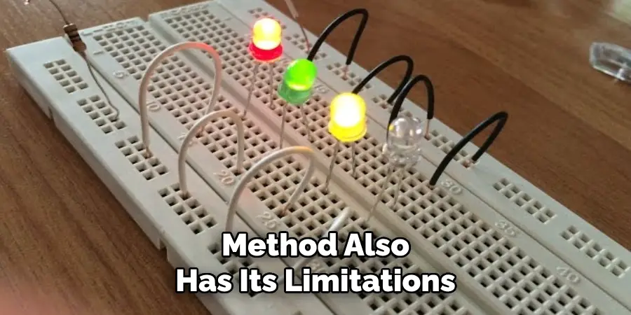
These are just some of the advantages of connecting LEDs in series. However, it is essential to note that this method also has its limitations.
What Will You Need?
To create a series connection of LEDs, you will need:
- LEDs: Make sure to choose LEDs with the same specifications (voltage and current rating) for a successful series connection.
- Resistors: Calculating the appropriate resistor value is crucial in a series connection. It helps limit the current flowing through each LED and prevents them from burning out.
- Soldering Equipment: Soldering is necessary to connect all the components in a series circuit.
- Power Supply: Depending on the voltage rating of your LEDs, you will need a suitable power supply to provide enough voltage for the circuit to function correctly.
Once all the components are ready, it’s time to start building your series circuit.
8 Easy Steps on How to Connect LEDs in Series
Step 1. Test Your LEDs
Before assembling the circuit, it’s crucial to test each LED individually to ensure proper functionality. Using a multimeter or a compatible power source, connect the positive lead of the LED to the positive terminal and the negative lead to the negative terminal. Observe if the LED lights up; a functional LED will emit light when connected correctly. Testing beforehand prevents you from integrating a faulty LED into your circuit, saving time and effort during troubleshooting. If any LED fails to light up, replace it with a new one immediately.
Step 2. Determine the Resistor Value
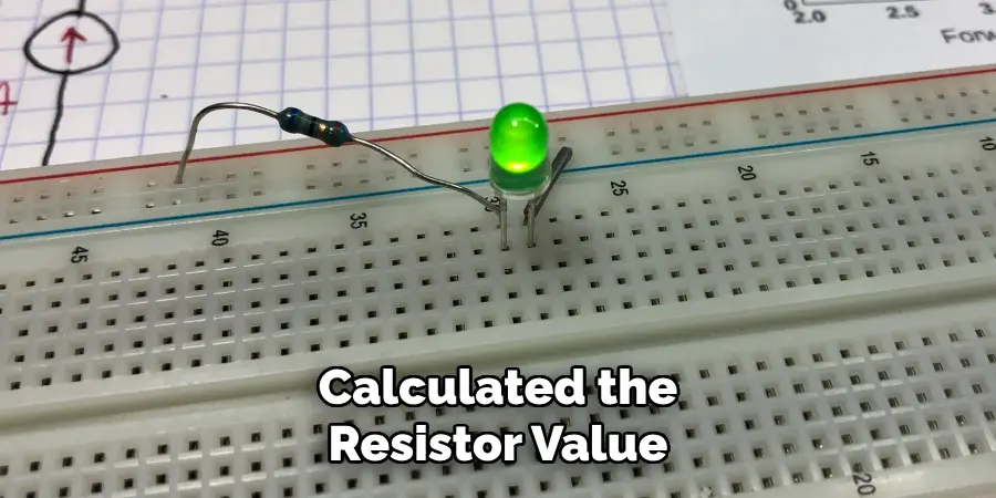
To determine the appropriate resistor value for your circuit, consider the LED’s operating voltage and current. LEDs typically have a specified forward voltage, which depends on their color and type, and a recommended current rating, usually in milliamps (mA). Using Ohm’s Law (R = V / I), you can calculate the resistor value needed to limit the current and prevent the LED from being damaged.
Start by finding the voltage of your power source and subtracting the LED’s forward voltage to get the voltage that needs to be dropped by the resistor. Next, divide this value by the desired current for the LED, ensuring you convert milliamperes to amperes by dividing by 1000. For example, if your power source is 5V, your LED forward voltage is 2.2V, and the operating current is 20mA (0.02A), the resistor value would be R = (5 – 2.2) / 0.02 = 140 ohms.
Step 3. Choose the Appropriate Resistor:
Once you have calculated the resistor value, it is vital to choose a resistor with a wattage rating that can handle the power dissipated by the circuit. This value can be found by multiplying the voltage and current values used in the previous step. Using a resistor with too low a wattage rating can cause it to overheat and fail.
In addition, it is recommended to use a resistor with a tolerance of 5% or less to ensure consistent performance. Resistors with higher tolerances may cause variations in brightness or other unexpected behaviors in your LED.
Step 4. Test and Adjust as Needed:
Once you have selected an appropriate resistor and completed the circuit, it is essential to test the setup thoroughly before using it in its final application. Begin by powering up the circuit and observing the LED’s behavior. If the LED doesn’t light up, double-check your connections to ensure that the resistor is placed correctly and all components are securely connected. If the LED is too dim or too bright, you may need to adjust the resistor value. Gradually fine-tune the resistance by swapping it with resistors of slightly different values until the desired brightness is achieved.
Step 5. Use a Multimeter
In addition to using a breadboard and resistors, you can also use a multimeter to measure the voltage, current, and resistance in your circuit. A multimeter is a versatile tool that helps troubleshoot problems with your circuit and provides valuable insights into its performance.
To use a multimeter, start by selecting the appropriate mode for the measurement you want to take (voltage, current, or resistance). Then, carefully place the multimeter probes on different points in your circuit to take readings. If you’re unsure where to place the probes, consult a schematic diagram or refer to online resources for guidance.
Step 6. Interpret the Readings
Once you have taken your measurements, interpret the readings carefully. Compare the values displayed on the multimeter with your expected results or the circuit’s specifications. If the readings deviate significantly, it may indicate an issue such as a bad connection, a faulty component, or an incorrect circuit design. Always double-check your setup and retake measurements if needed to ensure accuracy.
Step 7. Document Your Findings
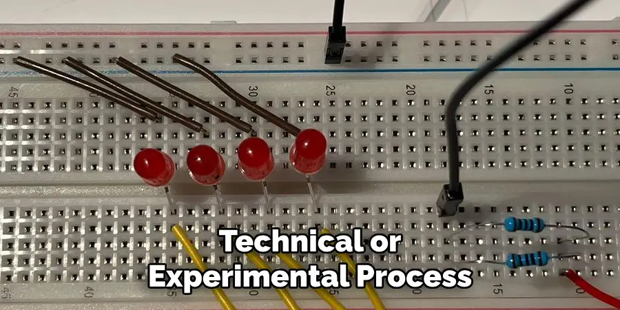
After interpreting the readings, it is crucial to document your findings accurately. Record the measurements, circuit configuration, and any observations in a dedicated log or report. Include details such as the date and time of testing, the multimeter settings used, and any anomalies or unexpected results. This documentation will help you track progress, analyze patterns, and troubleshoot issues effectively if they arise in the future. Clear and consistent records are an essential part of any technical or experimental process.
Step 8: Review and Verify Your Data
After completing your measurements and documenting your findings, it is essential to review and verify the collected data for accuracy. Cross-check the recorded values against expected results or theoretical calculations to identify any inconsistencies or errors. If discrepancies are found, repeat the measurement process to ensure reliability. Verification is a key step to confirm the integrity of your work and to build confidence in the conclusions drawn from your experiment or technical process.
By following these guidelines, you can ensure that your data is accurate and reliable, which is crucial in any scientific or technical pursuit.
5 Things You Should Avoid
- Skipping Resistors
Never connect LEDs in series without appropriate resistors. Resistors help regulate the current flowing through the LEDs, preventing them from overheating, which could lead to damage or failure.
- Using LEDs with Different Voltage Ratings
Avoid mixing LEDs with different forward voltage ratings in the same series circuit. This can cause uneven distribution of current, resulting in inconsistent brightness levels and possible damage to the LEDs.
- Ignoring Power Supply Limitations
Overloading the power supply by connecting too many LEDs in series can lead to insufficient power delivery. This may cause dim lighting or interruptions in the circuit’s functionality.
- Incorrect Polarity Connections
Ensure that the polarity of each LED is correctly aligned. Connecting the LEDs with reversed polarity can prevent the circuit from working and may harm the components.
- Improper Soldering or Loose Connections
Poor soldering or loose connections can cause intermittent faults or affect the circuit’s stability. Always ensure secure and neat connections for reliable performance.
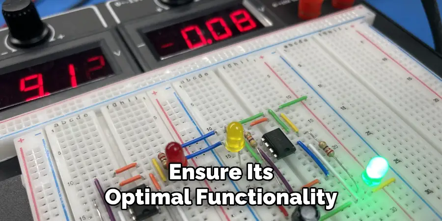
By avoiding these common mistakes, you can prevent potential problems in your circuit and ensure its optimal functionality.
Conclusion
Connecting LEDs in series is a simple yet effective method to create efficient and durable lighting circuits.
By ensuring proper polarity, using the correct resistor values to limit current, and maintaining secure connections, you can achieve reliable performance. This configuration is particularly well-suited for applications where consistent current flow through all LEDs is essential. Always test your circuit before finalizing to ensure that all components function correctly. With careful planning and attention to detail, connecting LEDs in series can provide long-lasting and energy-efficient lighting solutions.
Hopefully, this guide has provided you with a better understanding of how to connect LEDs in series.

